12" Fuel-Oil Transfer Line & Supports
Case History
12-INCH FUEL-OIL LINE
AND SUPPORT REPAIRS
AND SUPPORT REPAIRS
BioWrap 102 engineered composite reinforcement
Customer/site: Confidential
12-INCH FUEL-OIL TRANSFER LINE AND SUPPORT REPAIRS
Twenty-one engineered composite repairs completed across straight pipe, elbows and foot supports
21
repair areas
12 in
fuel-oil transfer line
4-6
BioWrap 102 layers
20 years
design life
Project overview
Asset and service conditions
- Location: Confidential - UK port fuel facility
- Asset: 12-inch fuel-oil transfer line and foot supports
- Service medium: highly viscous fuel oil
- Substrate: carbon steel
- Geometry: straight pipe, 45° elbows and foot supports
- Design / operating pressure: 16 barg / 14 barg
- Design / operating temperature: 50°C / 50°C
- Completion date: August 2024
Customer requirement
- Repair 21 areas of severe corrosion under insulation across approximately 250 m of pipeline.
- Restore pressure-retaining capability without isolating or draining the line.
- Reinstate the load-bearing capability of six corroded foot supports.
- Provide engineered repairs in accordance with ASME PCC-2.
Challenge
- CUI was concentrated predominantly at the 4-8 o'clock positions and accelerated by heat tracing and coastal exposure.
- Fifteen repair locations were assessed by NDT; six were too severely corroded for reliable readings.
- Measured remaining wall thicknesses at tested areas ranged from approximately 4.5 mm to 6 mm.
- Foot-support webbing created complex geometry that prevented suitable landing areas and laminate consolidation.
- The repair programme had to be completed while maintaining operational continuity.
Before condition
CUI affecting foot supports, straight pipe and localised repair areas
Before condition: severe external corrosion across the fuel-oil transfer line
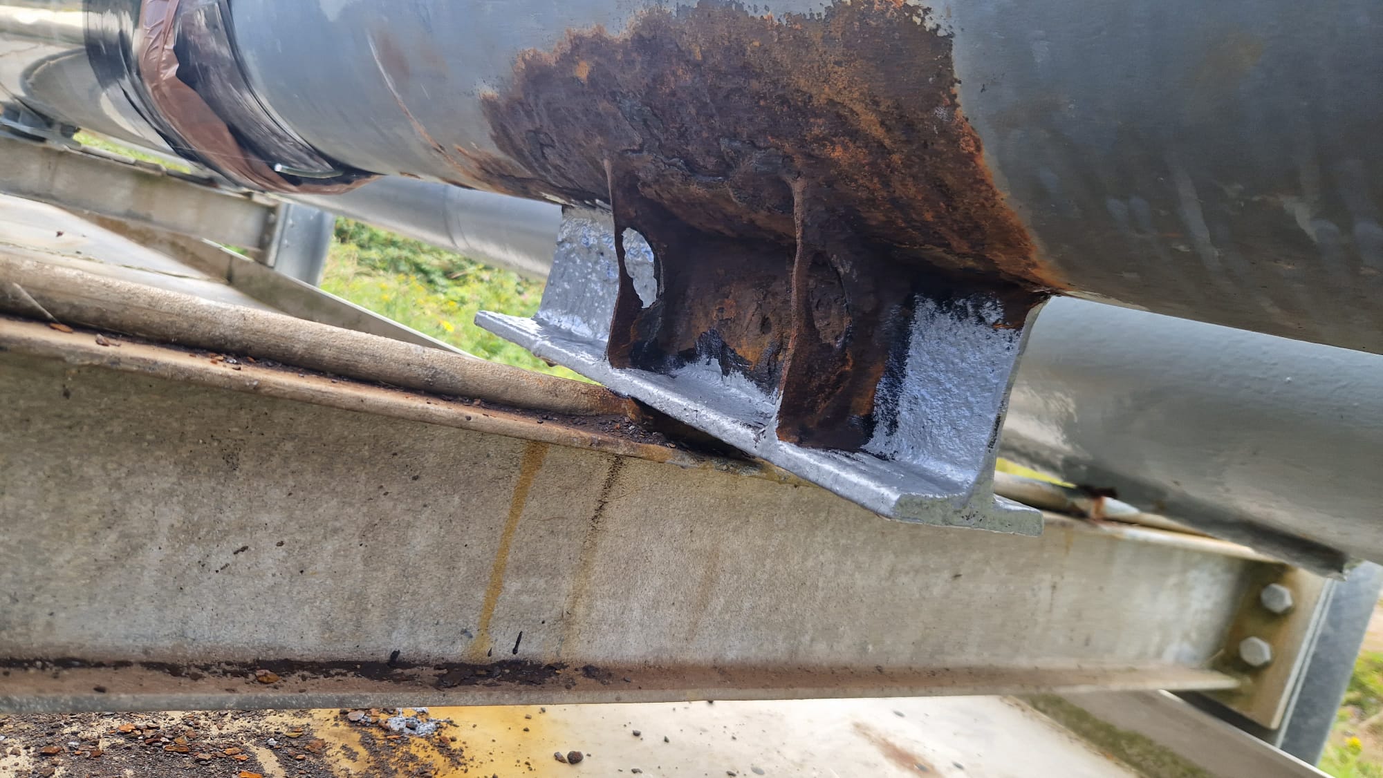
Corrosion under insulation affecting the underside of the line and a foot-support location.
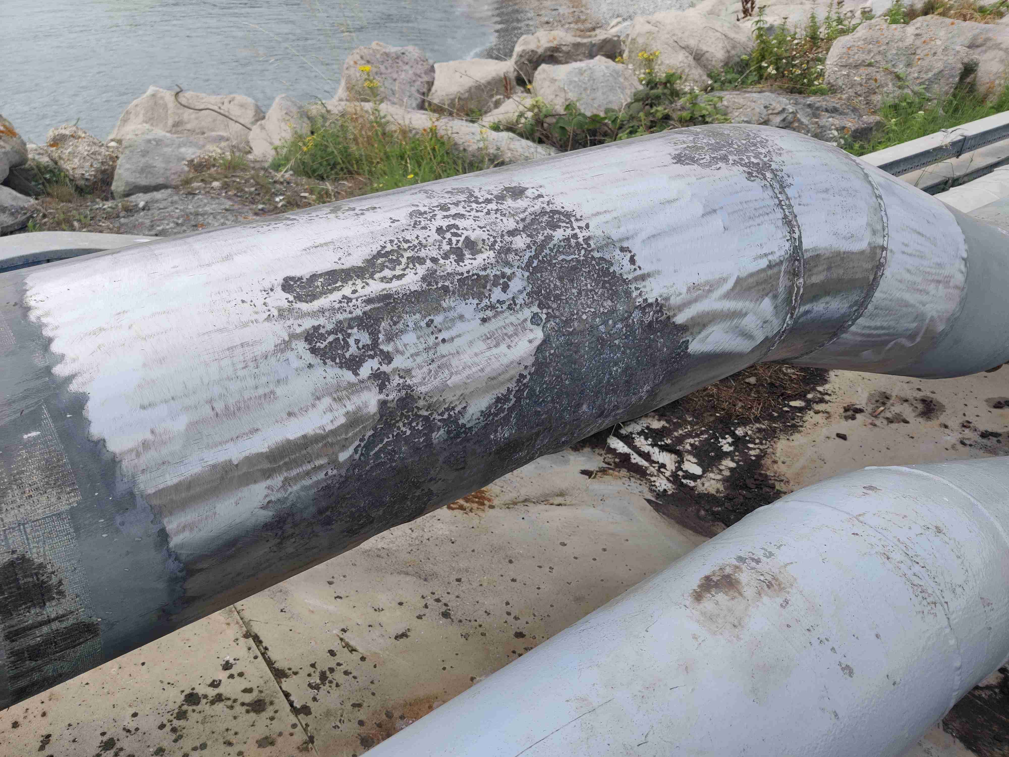
Localised external corrosion identified after removal of insulation and coating.
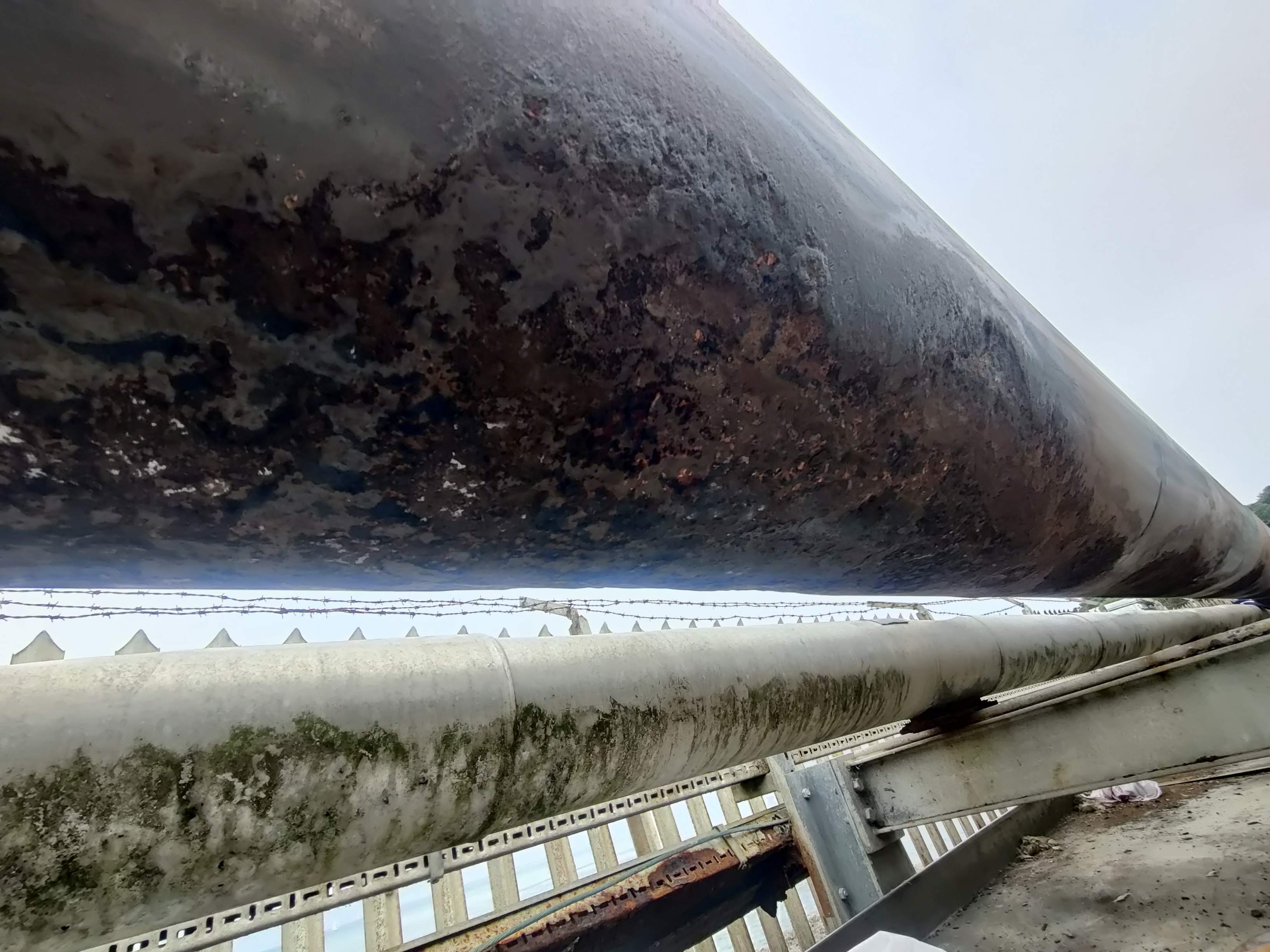
Severe CUI and wall loss at one of the 21 engineered repair locations.
Engineered repair method
01
Review and design
NDT data, defect geometry and operating conditions were reviewed for each location.
02
Surface preparation
UHP water jetting and rotary metal brushes achieved the required substrate condition.
03
Profiling
BindFast 1 and silica paste restored geometry and removed stress concentrations.
04
Composite application
Four to six BioWrap 102 layers were applied using tapes suited to each geometry.
05
Cure and sign-off
Repairs cured for 16 hours, were hardness checked and passed final QA inspection.
Repair data and technical controls
| Composite system | Repair areas | Layers applied | Design life |
|---|---|---|---|
| BioWrap 102 | 21 locations | 4-6 layers | 20 years |
Why this was a specialist repair
- The scope combined long straight-pipe repairs, elbows and complex foot-support geometries.
- Six locations were treated conservatively because corrosion prevented reliable NDT assessment.
- The foot-support repairs had to restore both pipe integrity and structural load-bearing capability.
Technical controls
- Surface preparation was completed to SSPC-SP 12 and SSPC-SP 11 requirements.
- Measured surface profiles ranged from 55 µm to 71 µm.
- Full cure was verified using Shore D hardness readings above 80.
- Final checks included laminate extent, thickness, tap testing and visual QA inspection.
Completed repairs
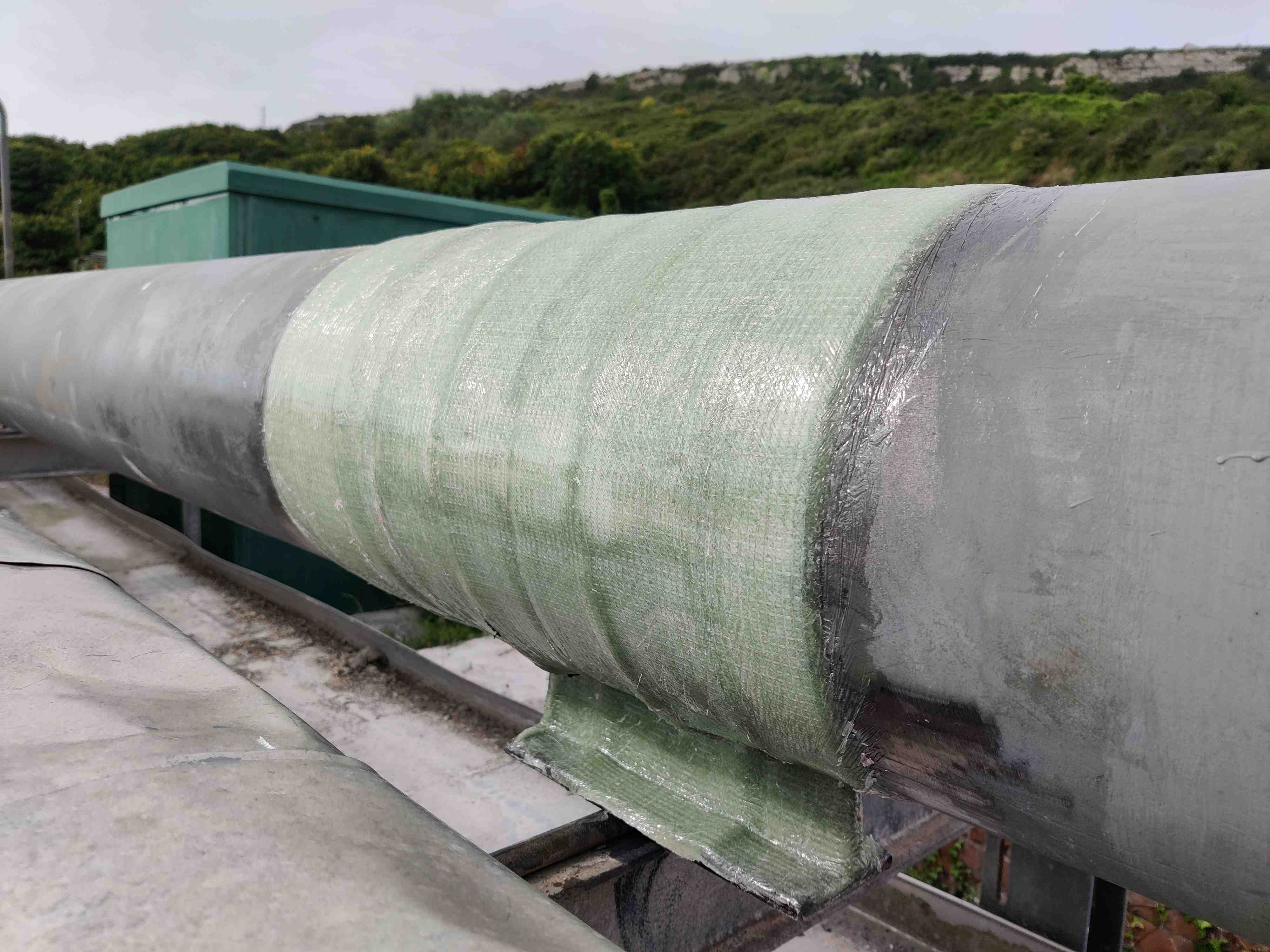
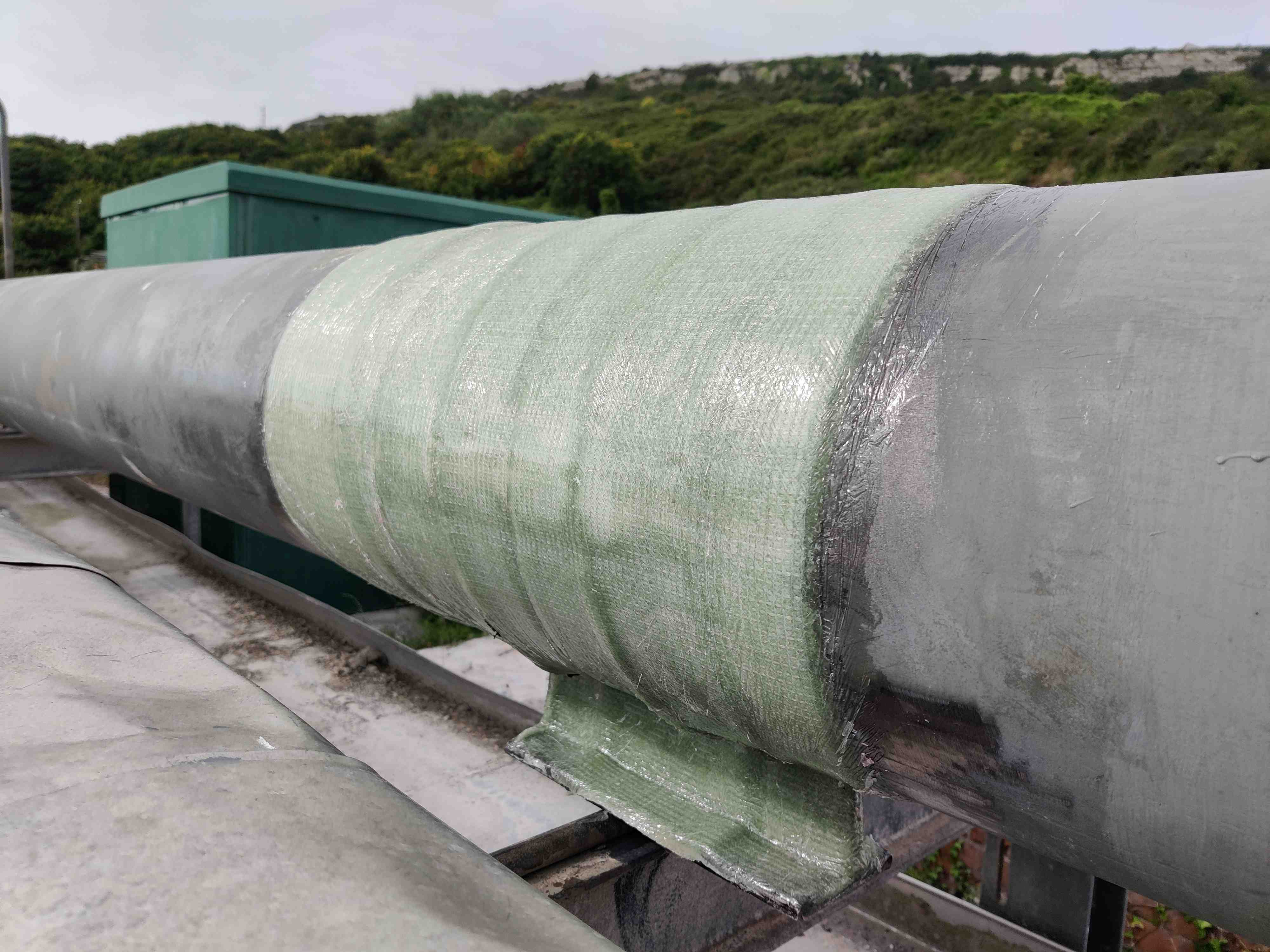
BioWrap 102 reinforcement across foot supports, straight pipe and complex repair geometry
Repair execution and completed fuel-oil line reinforcement
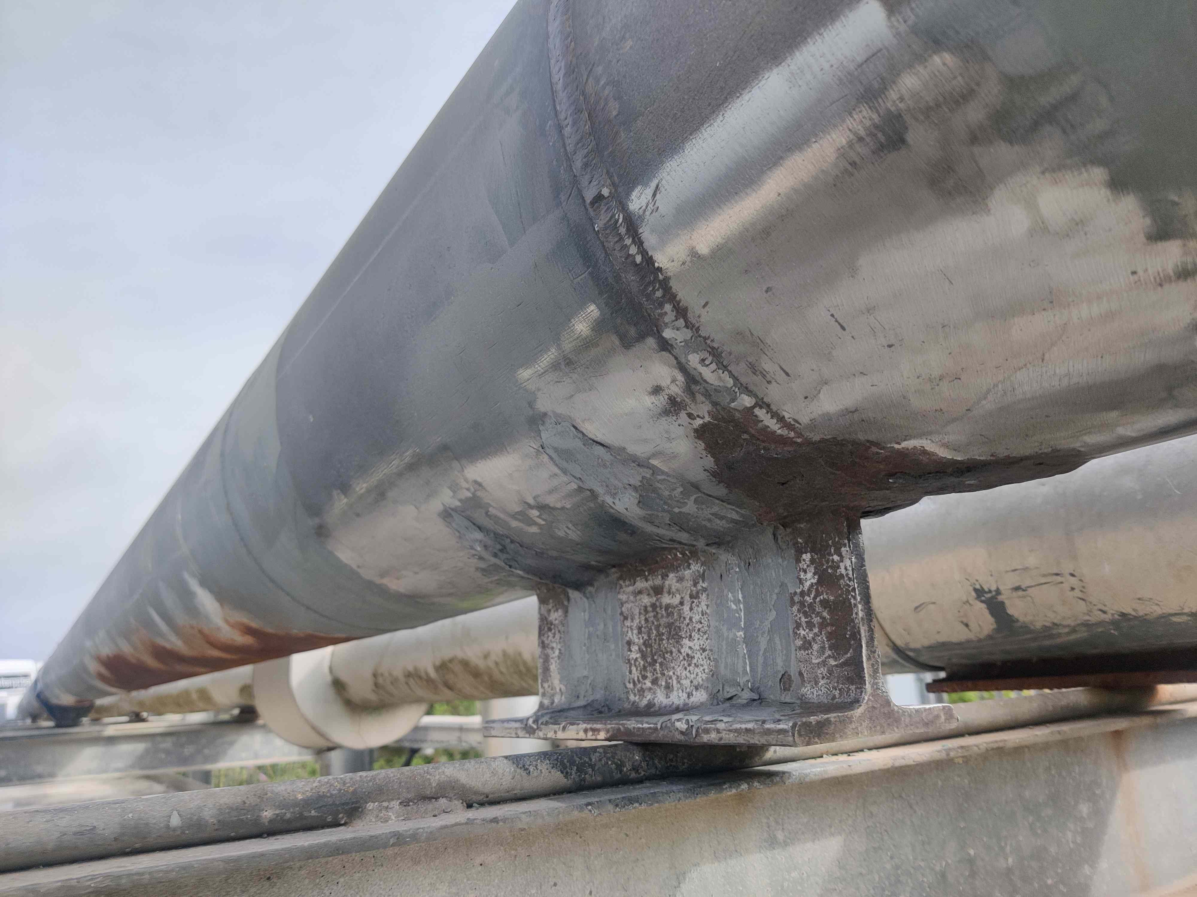
Completed BioWrap 102 reinforcement following controlled profiling and laminate consolidation.
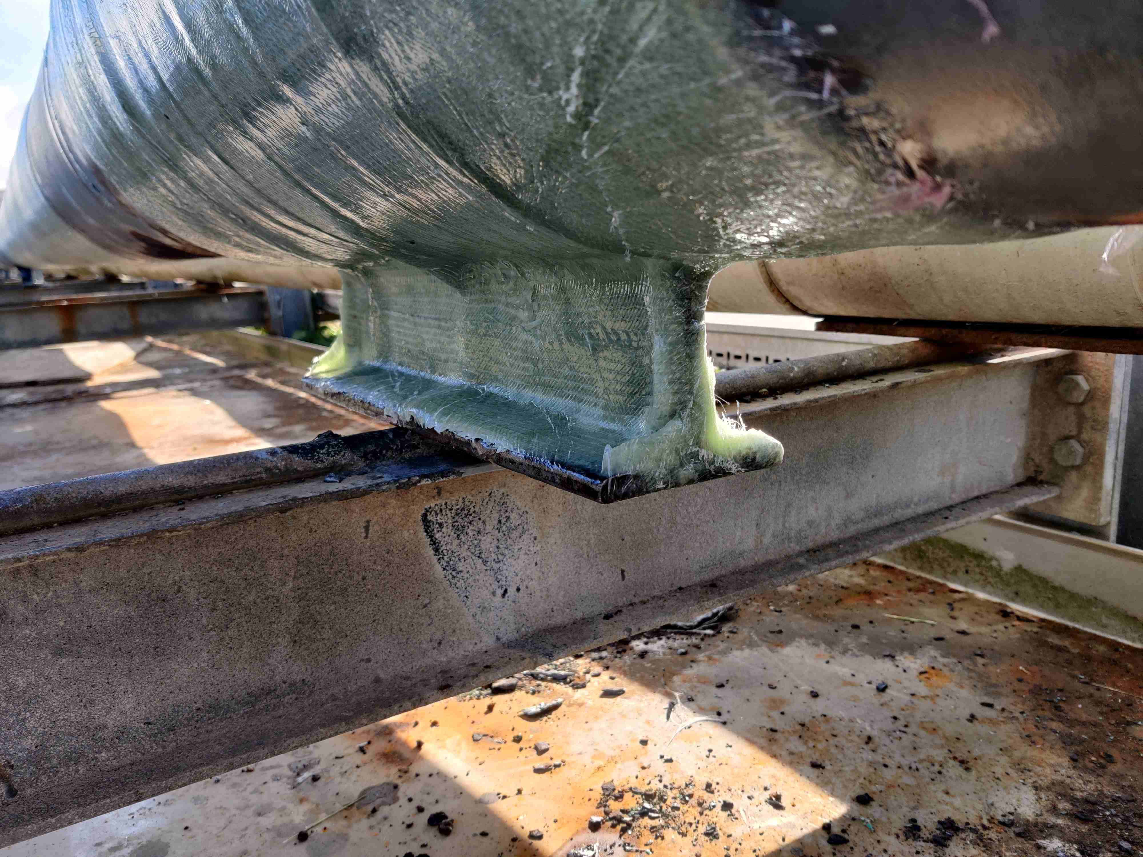
Composite repair formed around the support geometry while maintaining the required movement interface.
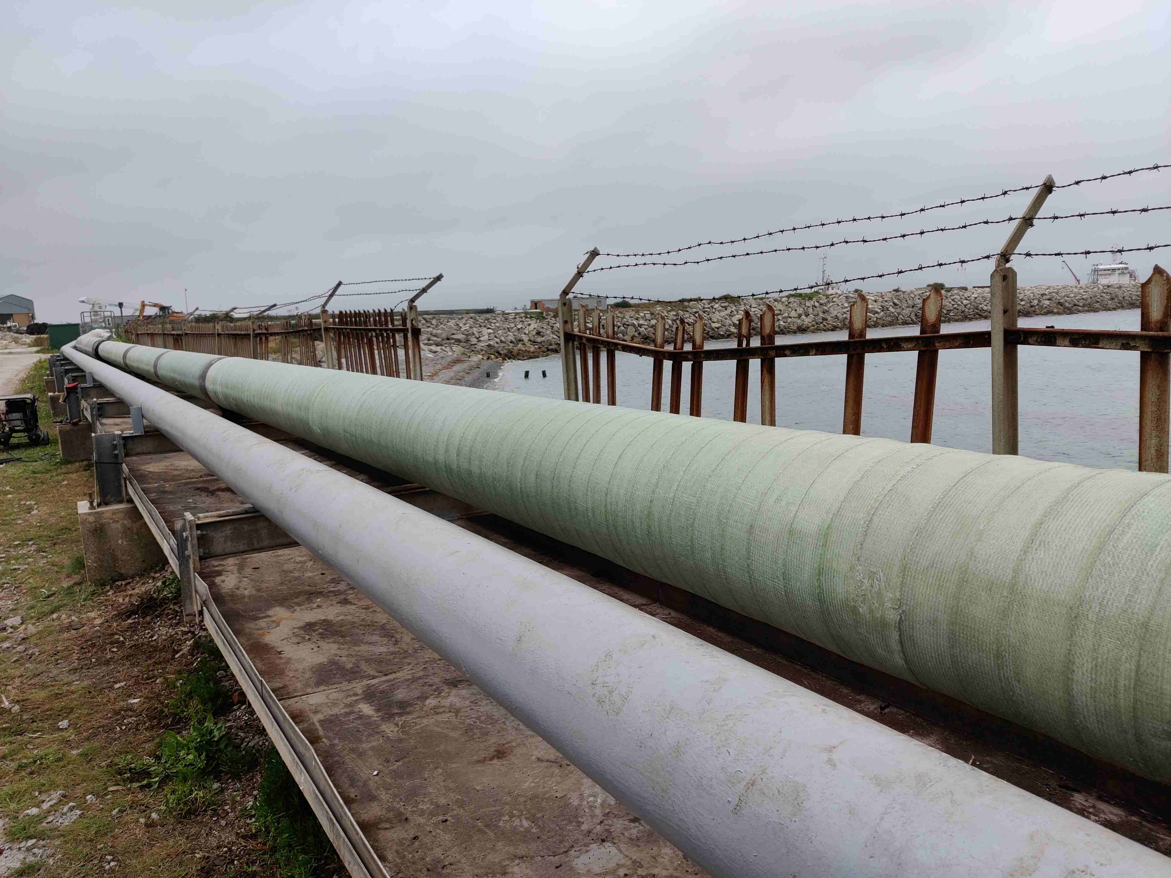
Completed straight-pipe repair providing structural reinforcement and external corrosion protection.
Outcome
What was achieved
- All 21 repair areas were successfully reinforced using BioWrap 102.
- Pressure-retaining capability was restored without isolating or draining the line.
- The load-bearing capability of the repaired foot supports was reinstated.
- Immediate replacement of the affected pipeline sections was avoided.
What this demonstrates
- Engineered composite repair of severe CUI across varied pipeline geometries.
- Controlled reinforcement of structural support locations as well as pressure-retaining pipework.
- Repeatable ASME PCC-2 repair delivery for fuel infrastructure in coastal service.
Need an engineered repair assessment?
Send the minimum engineering inputs and Icarus Composites can confirm feasibility, repair approach and the next technical steps.
01
Defect photos
02
Dimensions
03
Pressure / temperature / service
04
Required design life



