Fuel-Oil Suction and Discharge Lines CUI Repair
Case History
FUEL OIL SUCTION &
DISCHARGE LINE CUI REPAIR
DISCHARGE LINE CUI REPAIR
BioWrap 102 engineered composite repair
Customer/site: Confidential
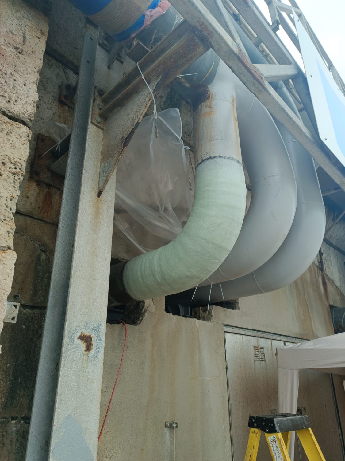
4”, 10” & 12” FUEL OIL SUCTION AND DISCHARGE LINE CUI REPAIR
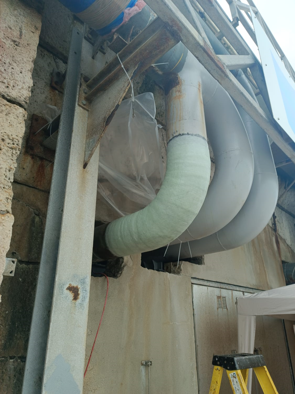
Live-line BioWrap 102 reinforcement after corrosion under insulation, clamp profiling and wall-thinning damage
11
repair areas
4-12 in
suction/discharge lines
4-8
layers applied
20 years
design life
Project overview
Asset and service conditions
- Location: Confidential - UK port fuel facility
- Asset: 4”, 10” & 12” suction and discharge lines
- Environment: onshore, harsh coastal exposure
- Defect type: corrosion under insulation and wall thinning
- Design / operating pressure: 16 bar / 14 bar
- Design / operating temperature: 50°C / 50°C
Customer requirement
- Restore line integrity without isolating or draining the affected lines.
- Overwrap a temporary non-engineered clamp after controlled profiling.
- Reinstate pressure-retaining capability using an engineered composite repair.
- Prevent further corrosion and avoid immediate pipe replacement.
Challenge
- Severe corrosion under insulation was detected at 11 locations across the suction and discharge lines.
- The CUI was predominantly at the 4-8 o’clock position and accelerated by heat-trace cycling and coastal exposure.
- A through-wall defect had already been sealed using a non-engineered clamp that had to remain in place.
- The work had to be completed without isolating or draining the line.
- Repairs were located at height and close to the pump room wall, creating restricted access.
Before condition
CUI, through-wall damage and temporary clamp detail
Before condition: corrosion under insulation and temporary clamp
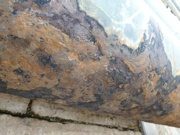
Corrosion under insulation and coating breakdown identified on the fuel oil line.
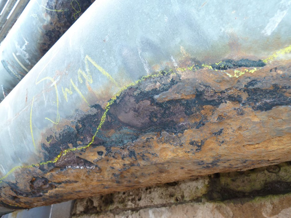
Severe external corrosion and wall thinning requiring engineered reinforcement.
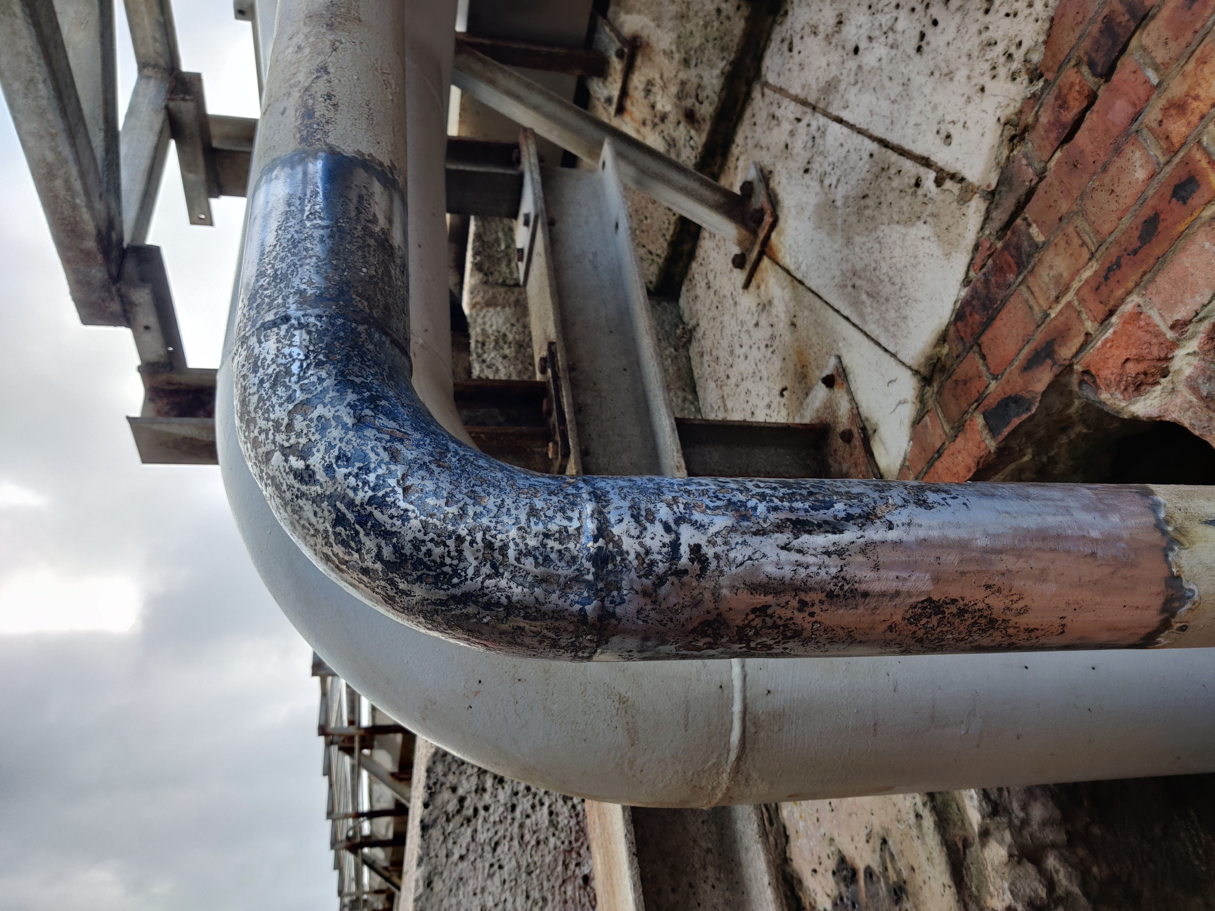
Temporary clamp remained in place because the line could not be isolated or drained.
Engineered repair method
01
Review and design
Defect locations and repair requirements reviewed before composite design.
02
Surface preparation
Repair areas prepared in restricted access and coastal site conditions.
03
Clamp profiling
Non-engineered clamp profiled with BindFast epoxies to create a smooth wrap profile.
04
Composite application
BioWrap 102 applied in accordance with ASME PCC-2 repair requirements.
05
Cure and sign-off
Repairs cured, checked and recorded with completion evidence.
Repair data and technical controls
| Composite system | Repair areas | Layers applied | Design life |
|---|---|---|---|
| BioWrap 102 | 11 repair areas | 4-8 layers | 20 years |
Why this was a specialist repair
- The repair had to be completed live, without isolating or draining the affected lines.
- A non-engineered clamp had to remain in place and be profiled before overwrapping.
- Restricted access at height and near the pump room wall increased execution complexity.
Source evidence used
- Case history IC-240418-01 and project repair documentation.
- Completion certificate, repair records and site photographs.
- Repair specification and calculation evidence for BioWrap 102 layer count.
Completed repairs
Clamp profiling, BioWrap 102 overwrap and completed live-line repair
Repair execution and completed BioWrap 102 repairs
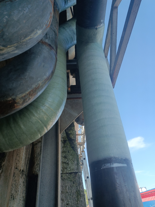
Profiled clamp and prepared repair area ready for composite overwrap.
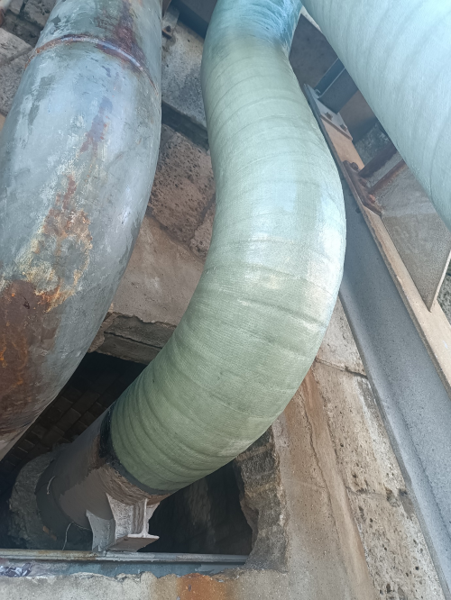
BioWrap 102 applied over the profiled clamp and adjacent repair area.
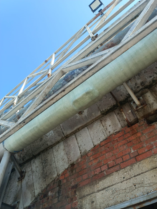
Completed repair restored pressure-retaining capability and external protection.
Outcome
What was achieved
- Clamp successfully profiled and overwrapped.
- Pressure-retaining capability of the affected lines restored.
- Further corrosion prevented through external composite protection.
- Immediate pipe replacement avoided.
What this demonstrates
- Live-line composite repair where isolation and draining are not available.
- Use of BioWrap 102 to overwrap difficult clamp and pipe geometry.
- Practical CUI repair for critical fuel-transfer infrastructure in coastal conditions.
Need an engineered repair assessment?
Send the minimum engineering inputs and Icarus Composites can confirm feasibility, repair approach and the next technical steps.
01
Defect photos
02
Dimensions
03
Pressure / temperature / service
04
Required design life



