Contents
Understanding Corrosion – Mechanisms and Root Causes Traditional Prevention Methods – Capabilities and LimitsWhen Corrosion Prevention Is No Longer EnoughEngineered Composite Systems – A Technical Deep DiveThe Icarus Composite Portfolio – Temperature-Stratified Solutions Solution Selection – A Comparative Decision FrameworkThe Icarus Composites Approach – From Assessment to Certified InstallationEngineering the Future of RepairIntroduction
Corrosion is not a surface problem. It is a structural degradation process that reduces wall thickness, compromises pressure containment, and systematically undermines the design assumptions on which your asset integrity strategy is built.
The global cost of corrosion is estimated at approximately $2.5 trillion annually, but the true cost in critical industries—oil and gas, petrochemicals, power generation, marine, mining, and nuclear—extends beyond maintenance expenditure. It directly affects:
- Remaining Strength Factor (RSF)
- Maximum Allowable Operating Pressure (MAOP)
- Fitness-for-Service (FFS) assessments
- Risk-Based Inspection (RBI) rankings
- Regulatory compliance and environmental exposure
This page serves as a comprehensive technical resource. It begins with fundamental corrosion mechanisms, examines traditional prevention methods and their limitations, and then addresses the critical distinction between corrosion control and structural rehabilitation—including when and how to apply engineered composite systems in accordance with ISO 24817 and ASME PCC-2.

Understanding Corrosion – Mechanisms and Root Causes
What Is Corrosion?
Corrosion is the electrochemical degradation of a material due to interaction with its environment. In industrial infrastructure, this most commonly affects carbon steel, low-alloy steels, stainless steels, and copper-based alloys used in pressure systems, tanks, structural members, and process equipment.
From a thermodynamic standpoint, refined metals exist in a higher energy state than their naturally occurring oxide forms. When exposed to oxygen, moisture, chlorides, CO₂, H₂S, or other reactive species, they undergo oxidation reactions that drive the material back toward a more stable state. In carbon steel, this results in iron oxide formation and progressive section loss.
Asset integrity implication: In pressurised systems, this degradation is not cosmetic. It reduces effective wall thickness (t), directly influencing:
- Hoop stress
- Burst pressure capacity
- Remaining Strength Factor (RSF)
- Fitness-for-Service (FFS) assessment outcomes
As wall thickness decreases, stress increases non-linearly. Localised defects such as pitting introduce stress concentration factors that can significantly accelerate failure.
The Electrochemical Fundamentals
Corrosion is fundamentally an electrochemical redox process. Four elements must be present for it to occur:
- An anode (where oxidation and metal loss occur)
- A cathode (where reduction consumes the released electrons)
- An electrolyte (ionic conduction path)
- An electrical connection (electron conduction path)
Remove any single element, and the corrosion cell collapses.
The Anodic Reaction (Metal Dissolution)
For carbon steel, the fundamental anodic half-cell reaction is:
Fe → Fe²⁺ + 2e⁻
Iron atoms lose electrons and enter solution as ferrous ions. This reaction physically removes metal from the substrate.
The Cathodic Reaction (Electron Consumption)
The cathodic reaction depends on the environment:
- In neutral or alkaline aerated environments (most external corrosion): Oxygen reduction dominates: O₂ + 2H₂O + 4e⁻ → 4OH⁻
- In acidic environments (low pH, CO₂ corrosion): Hydrogen evolution dominates: 2H⁺ + 2e⁻ → H₂
Corrosion Rate and Electrochemical Potential
The driving force for corrosion is the difference in electrochemical potential between anodic and cathodic sites. Using mixed potential theory (polarisation curves), the intersection of anodic and cathodic branches defines:
- Corrosion potential (E_corr): The mixed potential at which the system operates
- Corrosion current density (I_corr): Directly proportional to corrosion rate
Engineering interpretation:
- Reduce I_corr → reduce metal loss rate
- Shift E_corr more negative → more active corrosion
- Shift E_corr more positive → more noble (passive) behaviour
This is the theoretical foundation for all major prevention strategies: cathodic protection shifts potential, coatings reduce cathodic reaction area, inhibitors alter kinetics, and barrier systems remove electrolyte access entirely.
Classification of Corrosion Types
Corrosion in industrial infrastructure is classified first by location of attack—external or internal—and then by electrochemical mechanism. Understanding both is critical when selecting prevention or rehabilitation strategies.
External Corrosion
External corrosion affects the outer surface of pipes, tanks, structural members, and equipment exposed to atmospheric, buried, submerged, or marine environments.

CUI deserves particular attention. It is aggressive, expensive, and difficult to detect because it remains hidden beneath insulation. Cyclic heating drives moisture ingress and evaporation cycles. Damaged cladding, poorly sealed penetrations, and marine environments elevate the risk. From an integrity perspective, CUI is dangerous because degradation can be widespread yet invisible during routine visual inspections.
Internal Corrosion
Internal corrosion occurs on the process-facing surface of pipelines, tanks, vessels, and heat exchangers. Unlike atmospheric corrosion, rates are highly dependent on process chemistry, temperature, and flow regime.

Mechanism-Based Classification
Within both external and internal categories, corrosion manifests through specific mechanisms—each with a different structural risk profile.

Key takeaway: Uniform corrosion is predictable and manageable. Pitting, crevice, and CUI are the mechanisms most likely to cause unexpected failures. Knowing which mechanism you are dealing with determines your prevention strategy—and whether structural rehabilitation is required.

Traditional Prevention Methods – Capabilities and Limits
Traditional corrosion prevention methods are well-established and effective within their defined operating envelopes. They function by interrupting one or more components of the electrochemical circuit. However, they fall decisively into the preventative category: they slow or stop future degradation but contribute no structural reinforcement.
Protective Coatings (Barrier Systems)
Barrier coatings physically isolate the metal substrate from oxygen, moisture, and electrolytes. By removing the electrolyte from the corrosion cell, anodic and cathodic reactions are prevented.

Tape-Based Systems
Tape systems are widely used for buried pipelines, girth weld protection, and irregular geometry sealing.
Viscoelastic Anticorrosion Tapes (Primary Barrier)
Viscoelastic tapes are solid polyolefin-based systems that adhere tightly to steel and existing pipeline coatings, functioning as a primary corrosion-prevention layer.
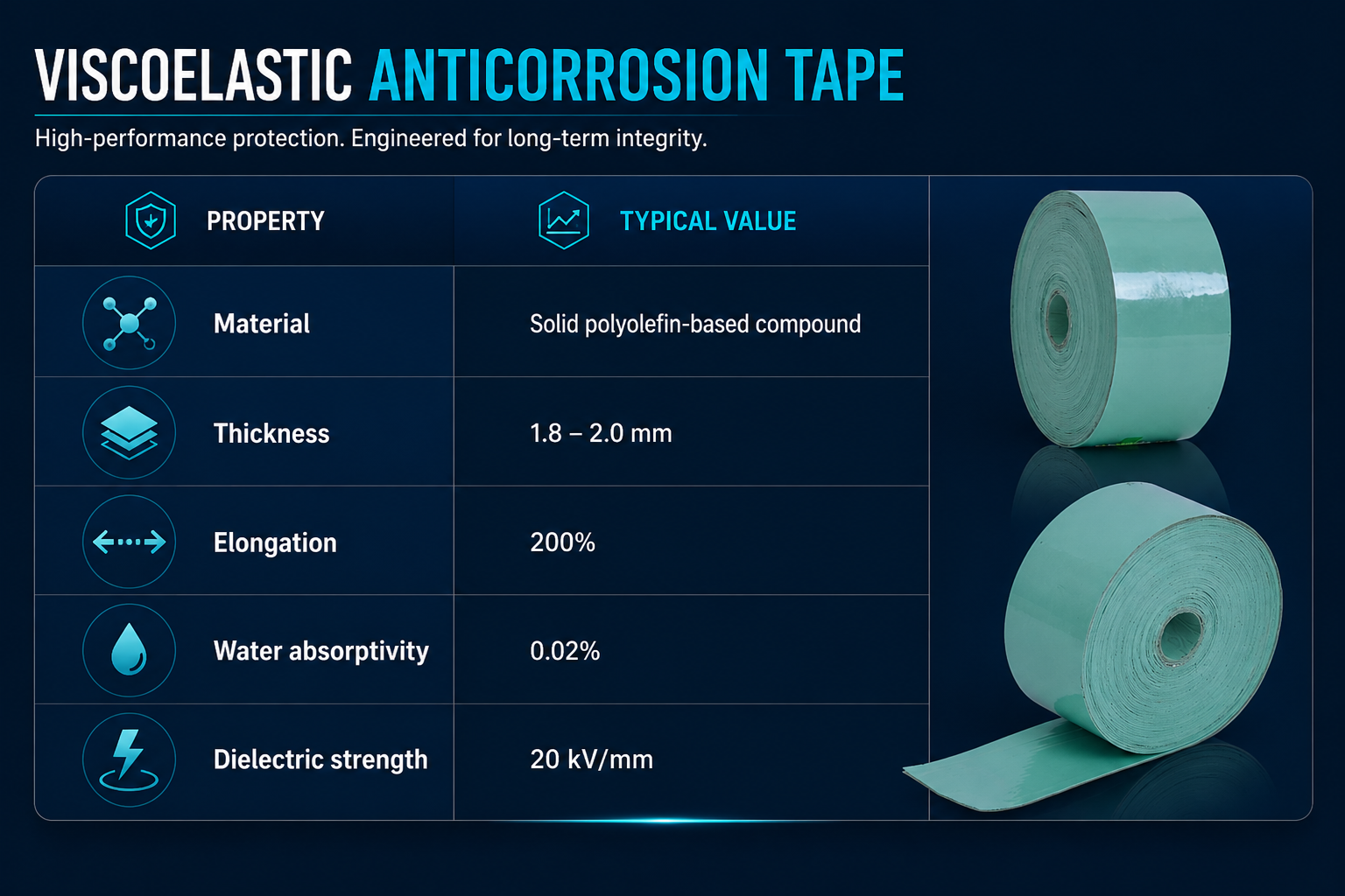
- Corrosion prevention mechanism: Forms a conformable, void-free seal adhering tightly to irregular geometries; eliminates oxygen and moisture ingress; self-heals minor mechanical damage through viscoelastic flow.
- Primary applications: Girth weld rehabilitation, flange and valve encapsulation, underground pipeline repairs, rehabilitation of existing PE, PP, and FBE coatings.
- Limitation: No structural contribution. Best suited for preventative corrosion control.
PVC Outer Wrap Systems (Mechanical Protection)
PVC outer wrap systems are designed primarily as a mechanical protection layer over corrosion-preventive coatings, not as the primary corrosion barrier.
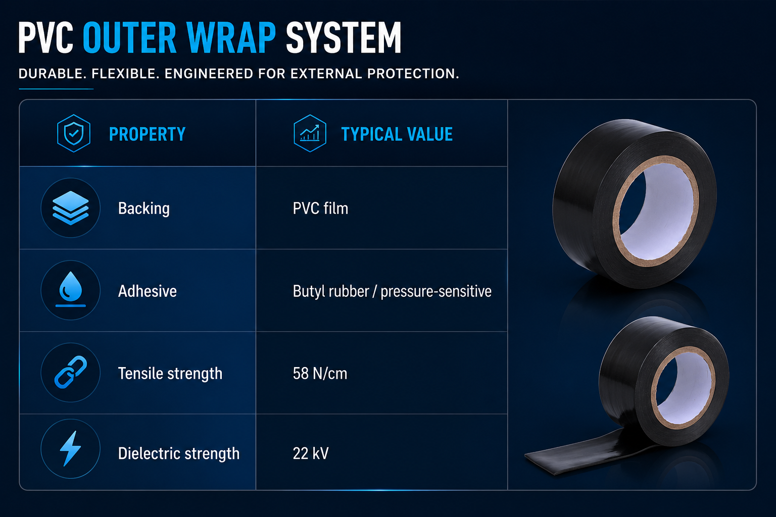
- Functional role: Protects underlying anti-corrosion coatings from soil stress and backfill damage; provides abrasion and UV resistance. Typically applied with 50% overlap.
Cathodic Protection (Electrochemical Control)
Cathodic protection (CP) shifts the potential of the protected structure to a more negative value, forcing it to behave as a cathode.
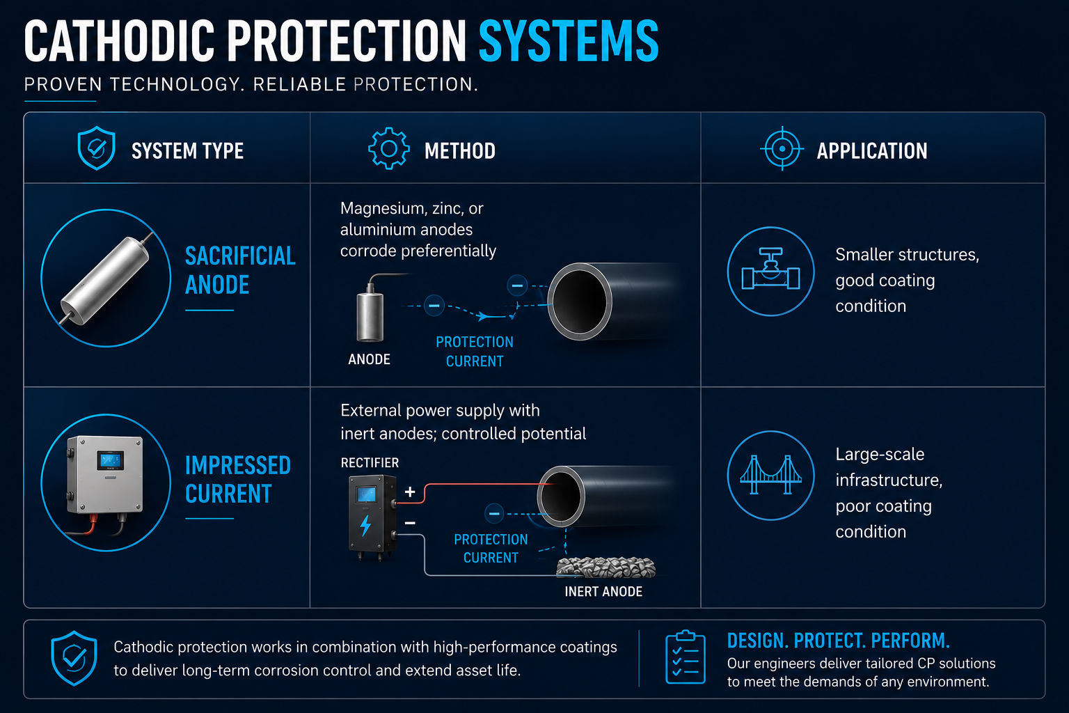
Advantages: Proven long-term technology; effective for large-scale buried and subsea infrastructure.
Limitations: Requires continuous monitoring; dependent on coating condition; does not restore structural integrity; stray current interference risks.
Corrosion Inhibitors (Environmental Modification)
Chemical compounds introduced into process streams to reduce corrosion rate by forming protective films, neutralising acids, or altering electrochemical kinetics. Common in oil & gas production, closed-loop water systems, and boilers.
Limitations: Ongoing operational cost; dependent on consistent chemical control; provides no structural restoration; only applicable to internal corrosion.
Galvanisation
Hot-dip galvanising coats steel with zinc, providing both barrier protection (zinc oxide layer) and sacrificial anode behaviour. Effective for atmospheric exposure with long service life in moderate environments.
Limitations: Not suitable for high-temperature systems; not applicable to in-situ rehabilitation; no structural reinforcement.
Material Selection (Alloy Upgrade)
Selecting corrosion-resistant alloys (CRAs)—stainless steels, duplex steels, Inconel, CuNiFe—can provide intrinsic corrosion resistance and reduced maintenance.
Limitations: High capital cost; fabrication complexity; not a practical rehabilitation pathway for existing assets.
Summary: The Preventative Ceiling
Traditional methods are essential and effective when applied proactively. But they share a common limitation: they cannot restore structural capacity once wall loss has occurred.

When Corrosion Prevention Is No Longer Enough
The decision point changes fundamentally once measurable wall loss, pitting, or localised defects appear. At this stage, the integrity assessment must transition from corrosion control to structural rehabilitation.
Consequences of Unchecked Corrosion
For integrity engineers and technical authorities, corrosion is ultimately a load-bearing problem:
- Reduction in pressure containment capacity
- Lower allowable operating pressures (MAOP downgrade)
- Increased inspection frequency and escalating RBI risk ranking
- Unplanned outages and environmental release events
- Regulatory exposure
In high-temperature systems, corrosion can combine with creep and thermal cycling. In offshore environments, chloride exposure accelerates degradation. In buried systems, soil resistivity and microbiological activity influence kinetics unpredictably.
The engineering question becomes: How do you restore structural capacity while isolating the substrate from further attack?
Traditional Structural Repair Methods
Where corrosion has resulted in significant wall loss, traditional intervention includes:

The gap in the market: What if you need structural rehabilitation without hot work, without extended downtime, and with corrosion isolation built in?
The Dual-Function Requirement
Effective rehabilitation of corroded assets requires two functions delivered simultaneously:
- Environmental isolation — deny the corrosion cell access to electrolyte, oxygen, and moisture
- Structural load sharing — redistribute hoop stress away from the degraded substrate
This dual function defines the transition from a coating to an engineered repair. Coatings provide the first. Only engineered composite systems provide both.

Engineered Composite Systems – A Technical Deep Dive
What Is an Engineered Composite Wrap?
An engineered composite wrap consists of:
- A high-performance polymer matrix (typically epoxy-based)
- A fibre reinforcement (commonly E-glass or carbon fibre)
- A defined laminate architecture (specified ply orientation and thickness)
When applied to a prepared substrate, the fibre-reinforced polymer (FRP) laminate bonds to the steel surface and cures to form a rigid structural shell. Unlike conventional coatings, composite systems are designed with calculated laminate thickness, defined mechanical properties (modulus, tensile strength, shear strength), and controlled curing behaviour—all compliant with recognised engineering standards.
The composite does not simply cover corrosion. It participates in load sharing.
Structural Reinforcement Mechanism
In pressurised cylindrical systems, hoop stress is the dominant stress component.
Where corrosion reduces wall thickness (t), hoop stress increases. An engineered composite wrap redistributes stress by:
- Bonding to the steel substrate
- Increasing effective section thickness
- Carrying a defined proportion of the hoop load
- Reducing stress concentration around defects (pits, thinned areas)
Load transfer occurs via interfacial shear between steel and composite. For properly designed systems, the composite laminate assumes part of the pressure-induced stress, effectively restoring the pressure capacity of the degraded section.
Barrier Protection Function
Simultaneously, the cured composite laminate provides:
- Very low permeability to oxygen and water
- Chemical resistance to hydrocarbons, acids, and salts
- Complete electrolyte isolation of the substrate
By removing electrolyte access, the corrosion cell is interrupted and further degradation arrested.
Composite wraps are therefore a single solution that delivers both:
- A structural reinforcement system (restoring load-bearing capacity)
- A corrosion isolation barrier (arresting further degradation)
Defect Types Addressed
Composite repair systems are used to rehabilitate:
- Uniform wall thinning
- External corrosion
- Internal corrosion (after process-side arrest or conservative estimates on defect growth)
- Pitting and localised defects
- Through-wall defects (with appropriate leak-sealing methodology)
- Erosion-corrosion zones
Design Standards and Engineering Basis
Engineering design is performed in accordance with internationally recognised standards:
- ISO 24817 — Composite repairs for pipework
- ASME PCC-2 — Repair of pressure equipment and piping
These standards define:
- Defect assessment methodology
- Laminate thickness calculation
- Design factors and safety margins
- Long-term performance considerations
- Qualification testing requirements
The result is a calculated repair with documented engineering justification—not an improvised patch.
Advantages Over Traditional Methods

Limitations
Composite systems do not replace cathodic protection in buried systems, nor do they eliminate the need for sound corrosion management practices. They are not a substitute for material replacement where degradation is complete. They are a rehabilitation pathway—designed, calculated, and applied where conventional coatings alone are insufficient but replacement is not yet justified.
The Icarus Composite Portfolio – Temperature-Stratified Solutions
Engineered composite systems must be selected based on operating temperature, environmental exposure, defect type, and required design life. Glass transition temperature (Tg), mechanical modulus, chemical resistance, and curing behaviour are the critical parameters.
Icarus Composites provides a temperature-stratified portfolio of ISO 24817 and ASME PCC-2 compliant systems, enabling engineers to select the appropriate laminate for the service envelope.
Ambient Temperature Systems (Up to ~82°C)
BioWrap 102™ — Structural Reinforcement for General Service
For water systems, hydrocarbon lines, storage tanks, and general process piping operating in moderate temperature environments.

Applications: External corrosion, uniform wall thinning, localised pitting, tank shell degradation, atmospheric and marine exposure.
Elevated Temperature Systems (Up to ~138°C)
Helios 158™ — For High-Temperature Process Piping
For steam tracing, hot process fluids, refinery lines, and industrial systems where resin thermal stability becomes critical.
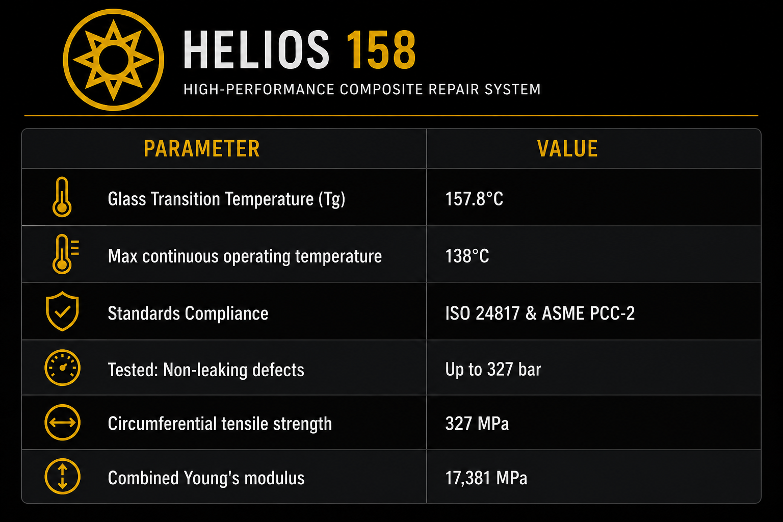
Key capability: Maintains stiffness at elevated temperatures; resists thermal softening; withstands thermal cycling.
Applications: High-temperature corrosion zones, steam lines, refinery process piping, chemical plant equipment.
Ultra-High Temperature Systems (Up to ~203°C)
Hyperion 223™ — For Severe Thermal and Chemical Service
For refinery, power generation, and chemical processing environments where extreme thermal exposure is continuous.

Note: Proper post-curing is required to achieve maximum Tg and thermo-mechanical stability.
Applications: Steam systems, high-temperature hydrocarbons, refinery units, power generation process piping, thermal cycling environments.
Subsea and Splash-Zone Systems
Oceanus 142™ — Water-Activated Composite Repair
For environments where corrosion exposure is continuous and electrolyte presence cannot be eliminated during application.

Applications: Subsea pipelines, caissons, marine infrastructure, potable water systems, splash-zone rehabilitation.
Key advantage: Water-activated prepreg format enables rapid deployment in environments where mixing conventional epoxies is impractical.
Preventative Systems (Non-Structural)
Not every corrosion application requires ISO 24817 design calculations.
UV-Curing FRP Shield
For assets where there is no significant wall loss and the objective is purely environmental isolation and mechanical protection.

Typical applications: Atmospheric corrosion protection, pipe racks and structural steel, insulation terminations, localised coating repair, protection of vulnerable geometries.
Important distinction: Where wall loss exceeds allowable limits, or where pressure containment must be restored, an engineered composite repair system designed to ISO 24817 or ASME PCC-2 is required. Barrier systems prevent corrosion progression. Engineered systems prevent corrosion and restore structural integrity.
Supporting Systems
PVC Outer Wrap — Mechanical Protection Layer
Flexible PVC tapes with pressure-sensitive rubber adhesive, designed as a mechanical protection layer over corrosion-preventive coatings.
- Impact, abrasion, and chemical resistance; UV resistant
- Applied with 50% overlap manually or via tape wrapping machine
- Application temperature: 0°C to +60°C
- Does not contribute to pressure containment
Viscoelastic Anticorrosion Tape — Primary Barrier Layer
Solid polyolefin-based compound designed as the primary corrosion-preventing inner layer, adhering directly to steel and existing coatings.
- Void-free conformable seal; self-healing behaviour
- Eliminates oxygen and moisture ingress
- Excellent resistance to aggressive soils and acids
- Applications: Girth weld rehabilitation, flange encapsulation, underground repairs
- No structural contribution
Portfolio Summary: Matching System to Environment

Solution Selection – A Comparative Decision Framework
Selecting the appropriate corrosion prevention or rehabilitation strategy requires balancing electrochemical control, structural integrity, operational constraints, and whole-life cost. No single solution is universally optimal.
Decision Factors

Consolidated Decision Matrix

Engineering Interpretation
- Preventative systems are appropriate where no structural degradation exists
- Structural systems are required once wall loss affects integrity
- Replacement is reserved for end-of-life or non-repairable assets
Composite systems occupy a unique position: cold-applied, structurally reinforcing, corrosion-isolating, and low-disruption—making them particularly suitable for ageing infrastructure where shutdown is not feasible and where both integrity restoration and corrosion arrest are required.
The Icarus Composites Approach – From Assessment to Certified Installation
Effective corrosion protection requires more than material selection. It requires a controlled engineering and execution process. The Icarus approach follows three stages.
Stage 1: Consultation and Data Collection
Asset data is gathered to define the problem accurately:
- Inspection reports (UT, MPI, visual)
- Operating conditions (pressure, temperature, cyclic loading)
- Defect sizing and characterisation
- Access constraints and geometry assessment
This ensures the repair strategy is based on verified asset condition—not assumptions.
Stage 2: Engineered Design
Repair calculations are performed in accordance with ISO 24817 and ASME PCC-2 methodologies, producing:
- Repair specifications and laminate thickness design
- Material selection based on temperature and chemical environment
- Installation procedures and acceptance criteria
This transforms the repair from a field decision into a documented, defensible engineering solution.
Stage 3: Certified Installation and QA/QC
Installation is carried out under controlled procedures, supported by:
- Surface preparation to recognised standards (typically Sa 2.5)
- QA/QC verification (laminate thickness, cure monitoring, adhesion testing)
- Full material traceability
- Completion documentation for integrity records
This ensures the installed system performs in line with the design assumptions and can be formally incorporated into your integrity management system.
Engineering the Future of Repair
Corrosion is thermodynamically inevitable. Structural failure is not.
The distinction at the core of effective integrity management is clear:
- Barrier systems interrupt the corrosion process
- Engineered composite systems interrupt the corrosion process and restore load-bearing capacity
By combining environmental isolation with calculated structural reinforcement in accordance with ISO 24817 and ASME PCC-2, composite systems enable asset owners to extend service life without replacement, maintain operation without shutdown, and restore integrity with documented engineering justification.
While paint buys you time, engineering buys you certainty.
Discuss Your Requirements
If you are responsible for critical infrastructure showing signs of corrosion, the next step is to define a solution that restores integrity, extends service life, and aligns with your operational constraints.
Our engineering team provides:
- Technical assessment of your corrosion challenge
- Standards-compliant design recommendations
- Material selection based on your operating environment
Need a repair? Contact our Engineering Team today
Ready to add engineered composite wraps and live leak sealing to your service portfolio? Tell us about your business and we'll get in touch.
Prefer to speak to us directly?
Contact our team and we'll guide you step-by-step on the journey to getting your assets repaired.
Phone:
+44(0)1706 334178
Email:
contact@icarusgroup.co.uk
Website:
www.icaruscomposites.co.uk
Location:
Cambridge, United Kingdom


